Autore

Documentazione PonyProg2000
Autore
Ultimo aggiornamento 18 Novembre 2000
Installing PonyProg depend on the system you have.
With Windows95/98 or NT/2000 just run the Setup.exe and follow the instructions.
With RedHat Linux 6.2 login as root, copy the ponyprog.tar.gz file in the root directory (cp ponyprog.tar.gz /) and then decompress it with the command tar xvfz, then you can remove the ponyprog.tar.gz file.
With other versions of Linux you need build the binary file from the sources.
You nned the V library v1.24 or newer correctly installed and the GNU g++ compiler.
If you want to use any parallel port interface you need also a 2.2.x kernel
and parport, parport_pc and ppuser kernel modules.
Before to start install the V library, I assume you have the symbolic link from
your home directory to v library directory (~/v is a symbolic link to the directory
you explode the v tar.gz, i.e. /root/v).
Login as root and follow these instructions:
Copy the file downloaded to a directory like /usr/local/src and decompress it
with "tar xvfz ponyprog.tar.gz", then enter the directory ponyprog.
Make a link to the V configuration file, the Config.mk in the root directory
of the V library:
"rm -f Config.mk; ln -s ~/v/Config.mk ./Config.mk"
Then build the executable and install it with "make linux; make installLinux"
for a static linked executable or
"make linuxelf; make installLinuxElf" for a dinamic linked executable.
The executable will be installed in /usr/local/bin. You must run it in X-Window
environment. Before to run the executable insert the modules into the kernel
(insmod parport; insmod parport_pc; insmod ppuser).
The first time you run the program remember to select the interface and port
you use with the Setup. If the program
report a message like "The interface don't respond" when started,
it means that you not have configured the port properly, or the interface is
not connected.
You need also to run Calibration in most
cases.
The following is an explanation of each menu command.
Open a new window, each window display a buffer for the device selected.
Open a file by name, and read its content in the current window. You can select the file to open through a dialog or drag and drop the file to open over the PonyProg window. PonyProg recognize several different types of file format: e2p, intel hex, motorola S-record and raw binary. If the selected file doesn't seem to be a e2p, it tries to open the file as intel hex; if this operation fails, then it tries to open the file as S-Rec; if also this operation fails, then it opens the file as binary. If the file has e2p format, you don't have to worry about the device type currently setted, otherwise you first have to select the correct device type, then load the file. In case of splitted Program/Data device like AVR and PIC the content of the data eeprom will be displayed after the content of the program flash memory in the current window with a different color.
This command is available only for splitted Program/Data devices. The buffer is splitted in two different part for these devices: the first part for program memory and the second part for data memory. This command Open a file by name and load only the program memory. You can select the file to open through a dialog. The file to load may have one of these format: intel-hex, motorola S-record or raw binary.
This command is available only for splitted Program/Data devices. The buffer is splitted in two different part for these devices: the first part for program memory and the second part for data memory. This command Open a file by name and load only the data memory. You can select the file to open through a dialog. The file to load may have one of these format: intel-hex, motorola S-record or raw binary.
Save the content of current window buffer to a file. If no name has been specified it works like Save as.
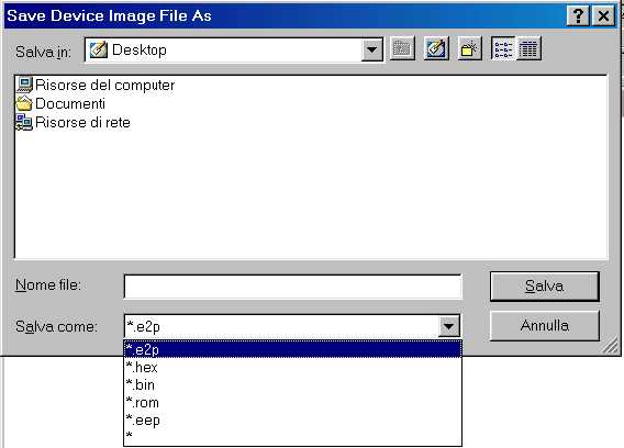
Open a dialog box where you can specify the name of the file. In the bottom of the dialog box you can select the file format for the file to save (indicated by the extension). If you press OK the content of the current window will be saved in the file specified. I suggest to save always in e2p format, doing so the device type and the notes will be recorded in the file. The .bin format is raw binary format, it's commonly used to export the file to other programs.
This command is available only for splitted Program/Data devices. The buffer is splitted in two different part for these devices: the first part for program memory and the second part for data memory. This command save the content of current window buffer program memory to a file. A dialog box asks you the name of the file to save and the file format by selecting the extension.
This command is available only for splitted Program/Data devices. The buffer is splitted in two different part for these devices: the first part for program memory and the second part for data memory. This command save the content of current window buffer data memory to a file. A dialog box asks you the name of the file to save and the file format by selecting the extension.
This command reload last opened files in the current window buffer. It's useful when you need to edit/build the files from an external program (assembler/compiler) and you need to repeat the same cycle: compile - load file - write device more than one time.
Open a dialog box where you can select the printer name and options. If you press OK the content of the current window will be printed.
Close the current window, if there is only one opened window a dialog window asks you if you want to exit; you can choose Yes or No. If the current window buffer is modified a dialog window asks you if you want to save the content in a file before to close the window.
Close all the opened window and exit the program. If there is a modified window buffer a dialog window asks you if you want to save the content to a file before to close the window.
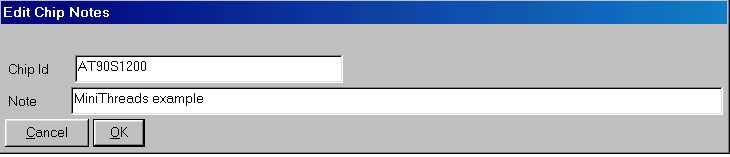
Open a dialog box where you can edit a Chip id and a note. These two fields are saved within the window buffer if you use the e2p file format (see Open). These two fields are free text editing, and are useful for a description of the device programmed and the meaning of its content.
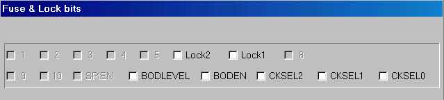
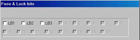
Open a dialog box where you can edit a device specific Configuration and Security bits. This dialog is especially useful for microcontrollers, because they could not work at all without set these bits in a correct way. The following screen dumps show the configuration bits for some microcontroller families. Note that disabled bits (grayed) are not used or not modificable.
AVR AT90S4433 Security and Fuse bits
PIC 16F84
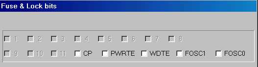
| FOSC1 | FOSC0 | Status |
| not checked | not checked | RC resistor/capacitor oscillator |
| not checked | checked | HS high speed crystal/resonator oscillator |
| checked | not checked | XT crystal/resonator oscillator |
| checked | checked | LP low power oscillator |
AT89S8252
Microchp 24C65
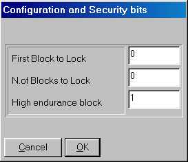
The dialog ask you to insert the first block and the number of blocks to lock. When the device is locked you can't do a "write security" or a "write high endurance" anymore. To lock the device the number of blocks must be greater than 0.
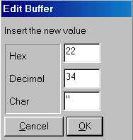
You can toggle this item either to enable or disable the edit mode. If the edit mode is enabled you can modify the buffer content by clicking on a location of the current window. Two editing modes are available: hexadecimal editing and text editing. If you click on the HEX (center) part of the screen or press ENTER you open a dialog where you can insert the new value for that byte in decimal, hexadecimal, or character. If you click on the ASCII (right magenta) part of the screen you open a dialog where you can insert or modify a text starting from that location. You can CUT & PASTE in the text entry dialog by the use of the right mouse button. Note that you can enable/disable only the edit mode of the current window, so if there are more than one buffer window opened, the edit mode of other windows are left unchanged.
Select the type of current device. You have to select the device type before
any commands (read, writing, open, save, ...). Selecting an "Auto XXX"
type means that the device type is determined by the program during the read
or write operation, this feature is useful when you need to query a device to
know if it works and which device it is. There are some different device family:
the I²C Bus eeproms that are addressed with 8 bit word, the I²C Bus eeproms
that are addressed with 16 bit word, the Microwire eeproms with 8 bit organization,
the Microwire eeproms with 16 bit organization, the SPI eeproms, the AVR microcontrollers,
the PIC 16 microcontrollers, the IMBus eeproms and SDE2506 eeprom. You can select
the device family in the tool bar with the combo-box, or directly the device
type in the menu. The current device type is stored in the .INI file, so the
next time you run the program it's recalled. To read and write I²C Bus eeproms
other than 24xx (i.e. the SDE2526, SDA2546, SDA2586, SDA3546, SDA3586) select
the type "24XX Auto".
The 24C01 can be readed but not writed, you can read it as a 2402 or 24XX Auto
device. Note that you can often replace a 24C01 eeprom with a new 24C02 eeprom,
because it's fully compatible to the 24C01.
Several microwire eeproms support two types of word organization: 16 bit organization
and 8 bit organization. The organization is selected with a pin connected to
VCC or GND. SI-Prog adapter connect this pin for 16 bit organization, however
some devices support only 8 bit organization.
Read the content of a device in the current window buffer. This operation
can take a while to execute, so a dialog box shows the operation progression.
If you want to stop the current read just press the "Abort" button.

Finally a dialog box showing the result of the operation appears.
If the program report the message "Device not responding" means that
you missed to connect the device to read, or the interface is not configured
properly (see the Setup). Note that only
the devices that support probing report this type of message, other device simply
read all 0's of FF's (if the device is missed). The devices that support probing
are the 24XX, the AVR and some PIC. In the case of AVR device selected,
the program can report the message "Device locked" in case of the
locked bits was programmed. Even some preproduction devices don't support auto
probing. You can't read a locked device, to program it see Write.
Since version 1.15c if you select an AVR device (AT90S2313
for example) and read it, the program try to probe the device first. If the
device is missing, or the device is locked, or the device is a preproduction
device a dialog box appears. It asks you if you want to abort operation, retry
or ignore the error. In case of a preproduction device just select "Ignore".

This command is available only for splitted Program/Data devices. The buffer is splitted in two different part for these devices: the first part for program memory and the second part for data memory. This command read only the program memory from the device, and leave the data memory intact.
This command is available only for splitted Program/Data devices. The buffer is splitted in two different part for these devices: the first part for program memory and the second part for data memory. This command read only the data memory from the device, and leave the program memory intact.
Read security and configuration bits from the device. Note that this command is implemented only for some devices. To modify the security and configuration bits refer to edit command.
Write the content of the current window buffer to a device. A dialog box ask
you to confirm this unrecoverable operation. This operation can take a while
to execute, so a dialog box shows the operation progression. If you want to
stop the current write just press the "Abort" button. After the write
operation an automatic verify is executed. Finally a dialog box showing the
result of the operation appears.
Before to perform a write I suggest to select the exact device type, not the
"24XX Auto" or "AVR Auto".
Note that both the program (FLASH) and data (EEPROM) memory are writed (only
if the device is a splitted device like the AVR or PIC), and then verified.
Since the version 1.15c a probe is performed on every AVR device (see Read).
This command is available only for splitted Program/Data devices. The buffer is splitted in two different part for these devices: the first part for program memory and the second part for data memory. This command write only the program memory to the device, and leave the data memory intact. The exception is the AVR device: to write the program memory an erase is needed, so the data memory is erased too.
This command is available only for splitted Program/Data devices. The buffer is splitted in two different part for these devices: the first part for program memory and the second part for data memory. This command write only the data memory to the device, and leave the program memory intact.
Write security and configuration bits to the device. Note that this command is implemented only for some devices. To modify the security and configuration bits refer to edit command.
Verify the content of a device, compares it to the content of the current window buffer. This operation can take a while to execute, so a dialog box shows the operation progression. If you want to stop the verify just press the "Abort" button. Finally a dialog box showing the result of the operation appears.
This command is available only for splitted Program/Data devices. The buffer is splitted in two different part for these devices: the first part for program memory and the second part for data memory. This command verify only the program memory from the device, and ignore the data memory.
This command is available only for splitted Program/Data devices. The buffer is splitted in two different part for these devices: the first part for program memory and the second part for data memory. This command verify only the data memory from the device, and ignore the program memory.
Erase all the content of a device to FF's (both program and data memory). Note that this command is implemented only for AVR and PIC devices.
Shows some informations about the device. Some of these informations are showed also in the status bar at the bottom of the main window.
Reset the device. It's useful with in-system applications.
Perform a configurable sequence of commands. You can select the commands to execute with program options
Select the commands to execute with the Program command.

Clear the current window buffer with FF's.
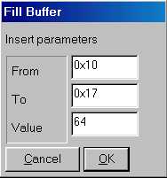
Fill the current window buffer with a character. A dialog box asks you to select
the addresses fo fill (from - to locations), and the value of the character
to fill. You can insert the value either in decimal (i.e. 45), hexadecimal (i.e.
0x45) or octal (i.e. 045) base.
This command duplicates every bank in the current buffer and changes the device type to a bigger device type. A bank is a cluster of 256 bytes for the 24xx and a word for other devices. This utility is useful to replace a SDA2546 device with a 24C08 or a SDA2586 with a 24C16. Example: you have to select the device type "24xx Auto", connect the SDA2546 device and perform a Read operation. Then you have to perform a "Double bank", replace the SDA2546 with a blank 24C08 and perform a Write operation (Refer also to I2CBus adapter).
This command swap bytes within every word in the current window buffer. It's
useful to convert from little endian representation to big endiand and viceversa.
Some devices uses 16bit word so you can represent it in both ways depending
on your needs.
For example consider the number 1234 hex (4660 decimal), the little endian is 34 - 12,
while the big endiand is 12 - 34.
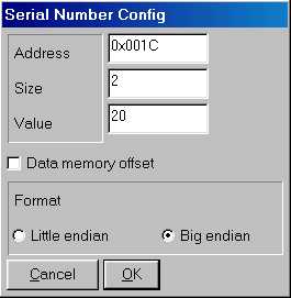
This command set the serial number in the configured locations of the current window buffer. You can configure the serial number location, value and size with the serial number config command. Every time you execute this command the value is incremented.
This command open a dialog box where you can configure the serial number locations,
value, format and size.
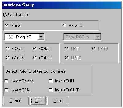
Open a dialog box where you can select the interface type and the port number where the hardware is connected. You can choose from several hardware interfaces (see PonyProg Hardware interfaces for more info). Note that only SI Prog support all devices.
Calibration tunes the serial bus speed for your computer. When you run Calibration
be sure that PonyProg is the only program running in the PC, and the hard disk
is idle (look at the HD led). If your PC is busy because it's performing other
tasks the Calibration thinks your PC is slower than actual speed, and all I/Os
are performed without proper delay.
After the Calibration you can choose the speed for every serial bus modifying the
following parameters in the ponyprog.ini (.PonyProgrc under Linux) file:
Every parameter can be assigned the value SLOW, NORMAL, FAST
or TURBO.
Avoid to use the TURBO value because it means "no delay", and
probably it doesn't work on your PC, especially with the I/O driver.
Just for example my PC (Pentium MMX 200MHz) run I²CBus at about 80Khz with NORMAL,
and 110 Khz with FAST. Note that a lot of I²CBus devices don't work
at speed above the 100KHz.
PonyProg supports several hardware interfaces, however note that only with
SI-Prog interface you are able to program all the devices.
Next paragraphs show all the hardware interfaces in detail.
Connect the DB9 connector to PC COM port using standard serial cable.
Connect J2 connector to the correct adapter observing polarity (look at pin
1 and pin 10).
This adapter is needed to program all I²CBus devices: 24C02, 24C04, 24C08,
24C16, 24C32, 24C64, 24C128, 24C256, 24C512, PCF858x and SDA2526, SDA2546, SDA2586
eeproms. Connect the adapter to main board observing polarity. Insert the eeprom
in the socket with the signature: 24xx (A0). If you need to access a 24xx eeprom
with SMT case (SO8) place the device with every pin exactly on the corrisponding
pad and press to make the contact good during the read/write operation.
Some devices mount two 24Cxx eeproms at different address and access them as
a large single eeprom. You can achieve this with the two sockets A0 and A2.
For example if you insert two 24C02 eeproms, select the "24XX Auto"
device and perform a read. PonyProg detect a 24C04 eeprom and the content is
the sum of the two 24C02 eeproms.
This adapter is needed to program the Microwire devices: 93C06, 93C46, 93C56,
93C66, 93C76, 93C86 eeproms. Connect the adapter to main board observing polarity.
Insert the eeprom in the socket with the signature: 24xx (A0).
Some devices mount two 24Cxx eeproms at different address and access them as
a large single eeprom. You can achieve this with the two sockets A0 and A2.
For example if you insert two 24C02 eeproms, select the "24XX Auto"
device and perform a read, PonyProg detect a 24C04 eeprom and the content is
the sum of the two 24C02 eeproms.
Version 2.2 of PDF mounting plan